 Troubleshooter

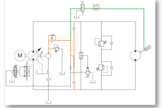
Below shows the hydraulic press diagram

Description of the hydraulic press diagram
This hydraulic press is operate by a low pressure pump and a high pressure pump. The pumps ensure rapid piston movement. That means a large quantity of oil at low pressure. The high pressure pump will raise the pressure when piston of the cylinder encounters resistance. Practically resistance comes from the pressing the product as required in the production sheet.
The check valves allows oil to pass in one direction, while blocking it when the flow is reverse.
Pressure limiting valves (pl1) is set at a specific maximum pressure from the HP pump and pl2 is set to a specific maximum pressure from LP pump by diverting the pump flow to tank. Also the pl1 and pl2 have a function of safety valves.
Control line in the hydraulic press diagram is arranged in such way that valve pl2 is also open if the high pressure pump in a system has a low pressure. E.g. Let’s say that the pl2 is set to open at 180 psi. If the HP pump in the system has a pressure of 180 psi or more the pl2 is open. Thus if the pressure in the system becomes more than 180 psi, valve pl2 is fully opened and LP pump will continue to circulate oil with no pressure.
Non-pressurized pumping by the LP pump have two advantages:
- Not so much heat is generate during the overflow of low pressure oil
- Consumption of electric motor power is limited during the process , therefore full power of the electric motor is available for the other pump respectively the HP pump.
Note about Pressure limiting valves
Pressure limiting valves in a hydraulic system opens when pressure set is reach or when pressure in the system increase over value set. This prevents the pressure in the system to become excessive.